Constraints take into account the intermediate transition from fully permitted to completely unusable, constraining the contact stress, bending stress, contact strength and flexural strength of the gear, geometrical constraints such as tooth width and index circle diameter, and design variables. The range of upper and lower bound constraints can be regarded as a fuzzy subset on the design space, so the constraints are as follows: (1) The contact stress H between the tooth surfaces should be less than the contact fatigue allowable stress []H, ie g1 ( X)=H=ZEZHZZcosmnZ12000(1 i)T1KAKVKHKHcosmnZ1id12[]H where: ZE elastic coefficient; ZH node area coefficient; Z coincidence coefficient; Z helix angle coefficient; T1 pinion torque (Nm); KA use coefficient; KV Load factor; KH tooth load distribution coefficient; KH tooth load distribution coefficient.
(2) The root bending stress F1 of the pinion gear should be less than the bending fatigue allowable stress []F1, ie g2(X)=F1=YF1Ysa1YYKAKVKFKF2000T1cos3m3nZ21d[]F1 where: the tooth profile coefficient of the YF1 pinion; Ysa1 pinion load Stress correction factor at the top of the tooth; Y coincidence coefficient; Y helix angle coefficient; KF tooth load distribution coefficient; KF tooth load distribution coefficient.
(3) The root bending stress F2 of the large gear should be less than the bending fatigue allowable stress []F2, that is, g3(X)=F2=YF2Ysa2YF1Ysa2F1[]F2 where: the tooth profile coefficient of the YF2 large gear; Ysa2 large gear load Apply correction factor at the top of the tooth.
(4) Since there is an intermediate transition between the gears from full use to no use, the contact strength and bending strength of the gears have a certain ambiguity. Therefore, the contact strength and the bending strength have a certain membership function (X) such that their fuzzy reliability R is Ri=Uf(Xi)(Xi)dXi(i=H, F1, F2) where Ri(i=H , F1, F2) respectively indicate the reliability of the gear in the three cases of tooth surface contact stress, pinion root bending stress, and large gear tooth root bending stress. Where: the normal probability density function of the f(X) stress.
According to the design requirements, the reliability Ri should be greater than or equal to the allowable reliability [Ri], ie Ri[Ri](i=H, F1, F2). (5) The coincidence of the helical gear should generally be greater than 2, ie g4 ( X) == 2.0: middle face coincidence; longitudinal coincidence. (6) The upper and lower bounds of the large gear index circle diameter are dg5(X)=imnZ1cosd(7) The upper and lower bounds of the tooth width are bg6(X)=dmnZ1cosb(8) The upper and lower bounds of the design variable are mng7(X)=mnmng8( X)=Z1g9(X)=Z1Z1dg10(X)=d Above the constraints, the values ​​of the upper and lower bounds must take into account the requirements of the specification, and also consider the design level, manufacturing level, material quality, use conditions, etc. The influence of factors, these factors have varying degrees of ambiguity.
The membership function of the fuzzy constraint should be determined according to the nature of the constraint. For the simple calculation, the following linear membership function is used here. The dynamic load factor of the gear is KV1.01.5, which is appropriate and is affected by many fuzzy factors. Here we consider the factors of the base pitch error, tooth shape error, circumferential speed, gear weight, meshing stiffness and transmission load. Using the two-level fuzzy comprehensive evaluation method [2], the KV is obtained as 1252.
What is appropriate is also affected by a variety of vague factors. We consider the fuzzy factors such as design level, manufacturing level, material quality, use conditions, importance and maintenance cost, and still use the second-level fuzzy comprehensive evaluation method to obtain equal to 0751. Thus the fuzzy optimization problem is transformed into the conventional optimization problem. In solving this conventional optimization problem, we use the internal penalty function method [3] to calculate the modulus and the number of teeth as continuous variables, and then round up the result.
Plastic Crates Making Machines
Meticulous division of labour, consecutive processes, professional of manufacture and high standard equipment ensure the high quality of the machine.
Factory introduced high precision maching tools, with the equipment of cutting machine tools, heattreating facilities, check out test sets and painting facilities, the processing ability for middle and large size machine, reach a high level in plastic industry while the quality if the machine is ensured at the same time.
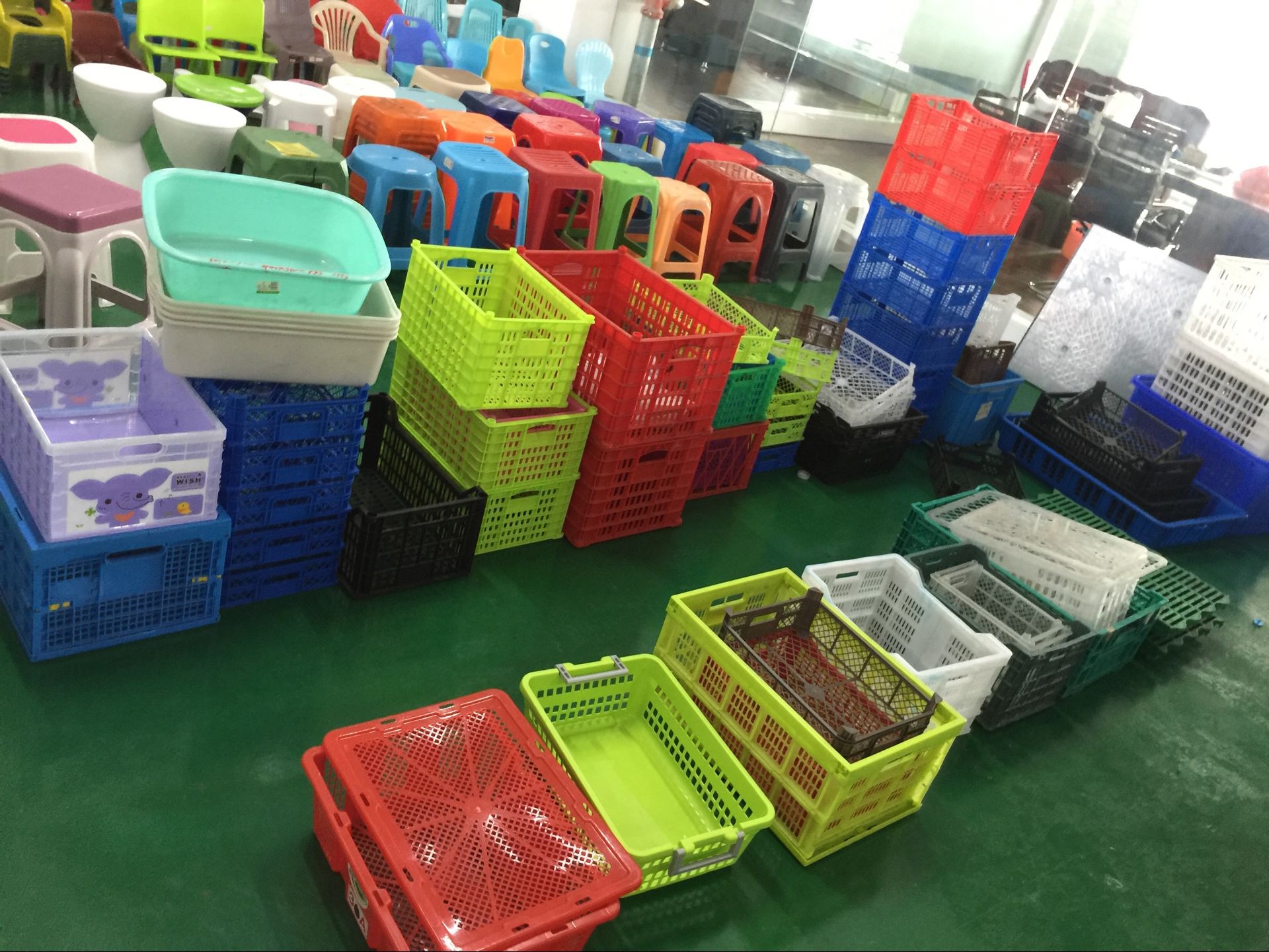
Middle size machine can produce differnt design of crates and containers, videos can be provided.
Vertification of many year's market application, optimal combination configuration, stable, reliable and durable system with the characteristics of high efficiency, energy saving, low voice and strong power.
The strengthening design of template is carried out through multiple times of optimization design of major components such as template, based on the analysis of finite element software, which both guarantee the lifetime of template and protected mould.
High rigid template adopts the structure with coexistence of installation screw hole and T-shaped groove.
The tie rod of each machine model has passed the test by professional testing organization, which means that, the deflection of tie rod is within reasonable scope while guaranteeing the operation of machine.

Plastic Crates Making Machines,Crate Making Injection Molding Machine,Crate Injection Making Machines,Plastic Basket Bucket Crate Making
Ningbo Tongyong Plastic Machinery Manufacturering Co. Ltd. , https://www.tongyongmachinery.com
