
First, the characteristics of the field bus and its application status With the continuous maturity of the field bus technology, more and more products support fieldbus technology agreement, and laid a good foundation for the application of fieldbus technology. Compared with traditional DCS, fieldbus technology has the following features.
(l) All-digital DCS analog signals are 4 to 20 mA. The field bus uses digital signals instead of 4 to 20 mA signals, so that the error correction and error detection of the analog signals can be realized and the signal transmission is more reliable.
(2) Interoperability and Interoperability Interoperability refers to the transmission and communication of information between devices that are connected to each other and between systems. Interoperability refers to the fact that products with similar performance from different vendors can be replaced with each other.
(3) The highly decentralized fieldbus control has a completely decentralized structure. The control function is realized by field devices. The process control function is realized by the control system installed in the control room.
Current DCSs that support fieldbus protocols include Siemens T-3000DCS, Emerson Corporation's OvationDCS, ABB's 800XADCS, and Xi'an Thermal Research Institute Co., Ltd.'s FCS165DCS. In addition to the FCS165DCS, other DCS support for fieldbus protocols requires the addition of fieldbus communication cards for data communication. This solution is a functional extension of traditional DCS and conforms to the current fieldbus protocol application status, ie not all control systems in the unit control. Both the equipment and the fieldbus technology are used, and some systems and equipment retain traditional instruments and non-intelligent equipment.
There are Profibus and FF2 types of fieldbus protocols used in thermal power plants. The control networks built with the Profibus protocol are the two types of protocols. The FF protocol is only applied to a few devices in Zouxian Power Plant and Huaneng Haimen Power Plant in Shandong. The application of the fieldbus-based control network began in the power plant's auxiliary shop control system application and has been gradually applied to the unit control system. The application scope is more and more wide, from the early data acquisition system (DAS) to the sequential control system (SCS). Until now, the FSSS and MCS have adopted field bus technology.
Second, the application of problems and countermeasures 2.1 Selection of bus types (1) determine the application of the field bus, the proportion of bus devices and meters, I / O control and security area ratio.
(2) Functionally consider the basic I/O information, bus power supply, and bus devices, including the bus protocol of the device, smart devices manufactured by different manufacturers on the same bus, bus communication cable length, redundancy, and diagnostic functions. If the equipment is in a hazardous area, consider using a bus with intrinsic safety features.
(3) In order to ensure the safe operation of the unit, the event sequence recording (SOE) function, FSSS, turbine emergency trip system (ETS), digital electro-hydraulic control system (DEH), feed pump turbine electro-hydraulic control system (MEH) and other Fast control systems are not easy to use field bus technology.
No type of fieldbus can cover all of the power plant's control range. Different types of fieldbus hybrid applications will be the trend. At present, the field bus technology application is still limited to the traditional DCS plus fieldbus communication card, the choice of bus type is limited by the type of DCS support protocol.
2.2 The design of the cable is not clear because of the design division of the field bus, resulting in the field bus cable can not fully comply with the design specification, the problem of interference and network segment speed reduction. In this regard, the design of the cable should be regulated. The maximum length of fieldbus segments at different rates is shown in Table 1 (length can be extended using repeaters).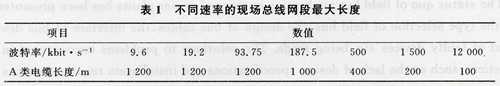
Cables are classified as:
(l) Category 1 Fieldbus and LAN cables (eg Profi-bus, AS-i, Ethernet, etc.), shielded cables for digital data transmission (eg printers, RS232, etc.), shielded low voltage (≤ 25V) analog and digital signal cable, low voltage (≤60V) power supply cable, coaxial signal cable.
(2) The second type of DC power supply (≤ 60V, ≤ 400V) power supply cable, AC power supply (> 25V, ≤ 40OV) power supply cable.
(3) The third type of AC and DC power supply (>400V) power supply cables and telephone line cables.
(4) The fourth category is the first three types of cables that have the danger of lightning strikes (eg, connected between different buildings).
The wiring principle is that the same type of cable can be arranged together, and the same direction cables can be arranged in the same cable slot. Different kinds of cables must maintain a certain distance from each other, and they must intersect orthogonally when they cross each other, and cannot have any parallel (even if a short distance) arrangement. The minimum distance between different types of cables is shown in Figure 1.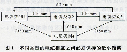
2.3 Connection of cables to fieldbus devices The interface of Profibus-DP devices is usually a 9-pin D-type connector. The D-type connector has 1 inlet and 1 outlet. The connection or withdrawal of the device connected through the D-type connector does not affect the connection. Segment cable connectivity. However, the communication interfaces of some bus devices are designed as ordinary terminals. The communication cable is connected to the terminals of the device. When the device needs to be replaced due to a fault, the communication cable after the fault device will be disconnected, which will cause the communication to be interrupted. In this regard, cables and fieldbus devices should be connected using D-type connectors.
2.4 Fault Replacement (l) When the traditional equipment fails to be replaced, as long as the equipment type and specifications are the same as the faulty equipment, the I/O cable is reconnected after replacement. After simple debugging, the system can work normally, and the DCS control configuration does not need to be modified. There are two kinds of situations when the fieldbus equipment fails to be replaced. First, the replacement equipment is the same as the faulty equipment type, model, specification, and manufacturer, and there is no need to replace the driver file (GSD) file. After the replacement, the control configuration does not need to be modified; the second is replacement. The equipment is consistent with the type, model, specification, and manufacturer of the faulty equipment. Different GSD files require DCS reconfiguration and debugging (including equipment commissioning) after replacement. Failure of the device and different manufacturers, and the type, specification of the same device or a device of the same type and size of the device after the replacement can not make it work properly, because the GSD file of the fieldbus intelligent device is different, the signal definition of the device It is also different, so there is no uniform standard and norm. To this end, it is necessary to formulate signal transmission specifications for smart devices on the fieldbus, specify the type, number, and order of signal transmission of the same type and specification device, that is, the types of fieldbus intelligent devices of the same type and specifications, and the types of transmission signals. The order of signal transmission must be the same.
(2) Fieldbus devices (smart meters, electric gates, etc.) are faster than DCS, making DCS not support the latest production of field devices. Normal use of field smart devices in DCS requires device driver software, while DCS is not a unified, open system, and DCS upgrades are required to support new fieldbus devices. This phenomenon is particularly prominent when fieldbus control systems consisting of FF bus protocols are used. In this regard, DCS can be tested and system upgraded to improve DCS's ability to support on-site smart devices.
III. Conclusion (1) At present, the application of fieldbus technology lacks corresponding requirements such as design specifications, installation, data transmission of smart devices, and communication interfaces, which causes some problems in engineering applications. The formulation and implementation of relevant standards and norms play an important role in giving full play to the characteristics and advantages of fieldbus technology.
(2) With the development of digital technology, field instruments and functional modules with more powerful functions have been continuously produced, and fieldbus lays the foundation for the realization of a fully digital power plant.
(3) The essence of fieldbus technology lies in all informatization and intelligence. Its integration and processing of equipment information will greatly change the mode of management and maintenance of equipment in power plants, increase the service life of equipment, and reduce maintenance costs. The larger the application of fieldbus technology, the more obvious the advantages of improving the control performance of the unit and saving the overall cost (including design, construction, maintenance, etc.).
Household Sanitary Ware DFC system
Wood safety box Integrated stove Smart toilet lid TV stand are common household items. Their grinding processing at present are manual, the force imposing on the Grinder is not consistent, most are based on technician experience or technique. Our Force Control System can flexible control the force imposing on the grinder, quick response to the surface changing, and instant adjusting the force on the grinder.
wood DFC system, safety box DFC system, Integrated stove DFC system, Smart toilet lid DFC system, TV stand DFC system
DARU Technology (Suzhou) Co., Ltd. , https://www.darudfc.com